Gas Springs – Useful informations
Gas Springs range selection
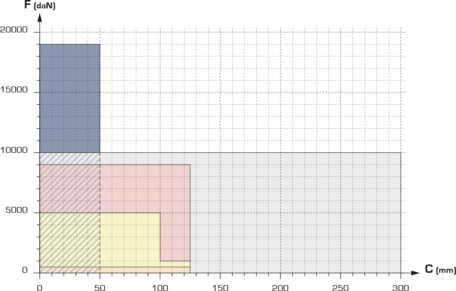
| Micro | High power | Super Compact | Low profile | ISO |
|
RG19 RMG RMGE MRG RG32 RG300F
|
RGP
RGT |
RGC | RGH | RG |
| Diameter | Diameter | Diameter | Diameter | Diameter |
| 19 to 38 mm | 19 to 150 mm | 25 to 150 mm | 45 to 120 mm | 38 to 165 mm |
| Force | Force | Force | Force | Force |
| 30 to 300 daN | 170 to 9500 daN | 420 to 18300 daN | 500 to 5000 daN | 250 to 10000 daN |
| Stroke max : 125 mm | Stroke max : 125 mm | Stroke max : 50 mm | Stroke max : 125 mm | Stroke max : 300 mm |
| See Micro products | See RGP productsSee RGT products | See RGC products | See RGH products | See ISO products |
General recommandations
• Gas springs are filled with high pressure Nitrogen and should not be repaired by non trained people.
Never try to open a gas spring if you haven’t received a specific training.
• Never grind or weld near a gas spring.
• Never modify nor machine a gas spring.
• Never strike two gas springs rods against each other (the slightest mark on the piston rod may lead to a loss of pressure in the spring).
• Never fill gas springs with a pressure higher than indicated on the body.
• Never use a gas spring for other function than according to the catalogue.
• Never fill a gas spring with other gas than nitrogen.
Using other type of gas could result in personnal danger.
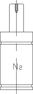
• Operating temperature : 0 to 70°C.

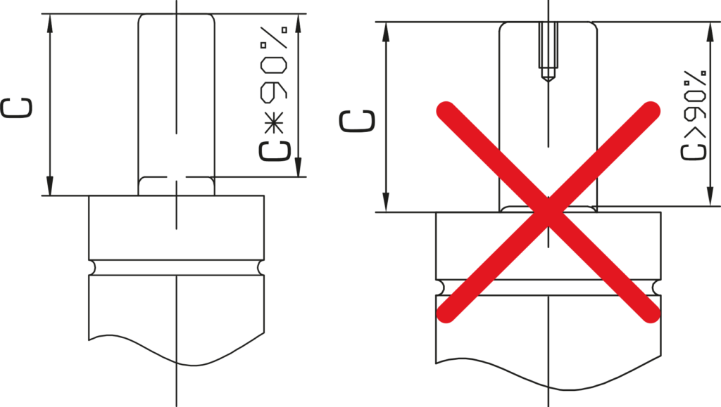
• Gas springs will permit travel of the full nominal stroke; however, a 10% stroke reserve is recommended to achieve optimal performance and safety.
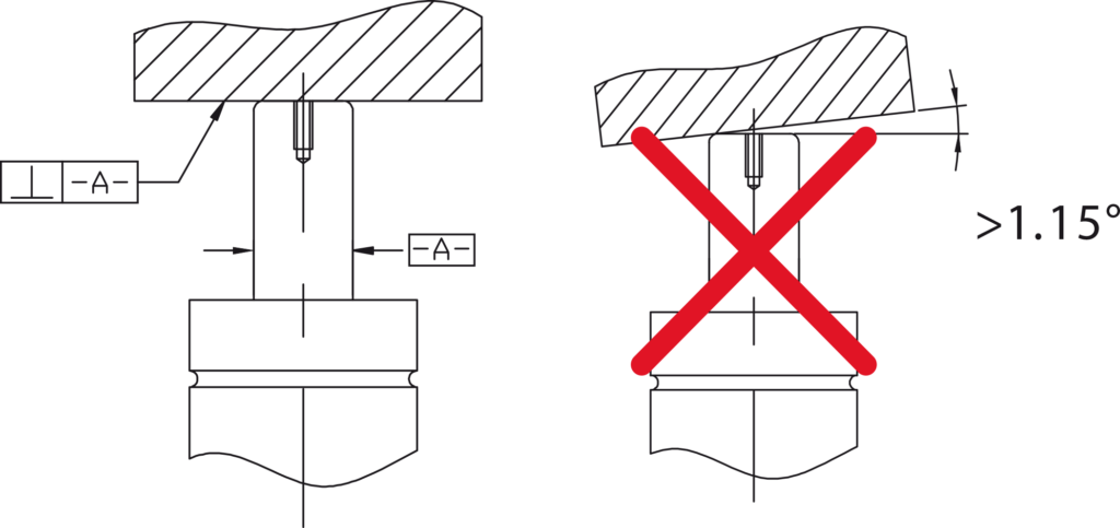
• Avoid side loading when possible. A misaligned press or die can cause side loading that increases wear on the bearing, seal and piston rod.
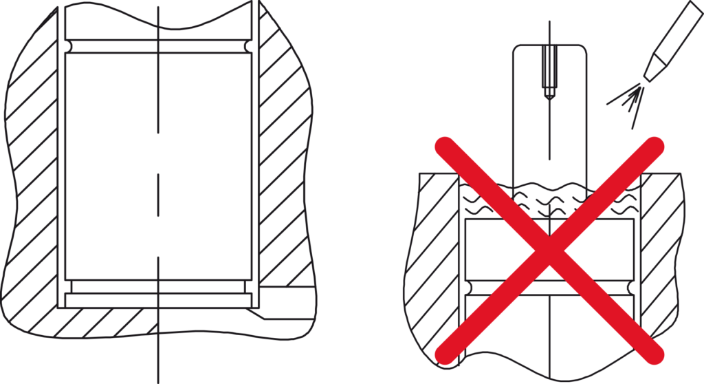
• Protect gas springs by providing adequate drainage in gas spring pockets. Direct contact with certain die lubricants and cleaners should be avoided.
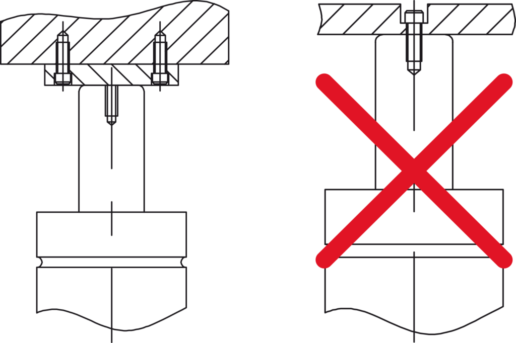
• The end of the piston rod has construction thread intended for assembly and disassembly only.
Never to be used to mount or secure the gas spring.
Die vibration and/or misalignment will damage the spring.
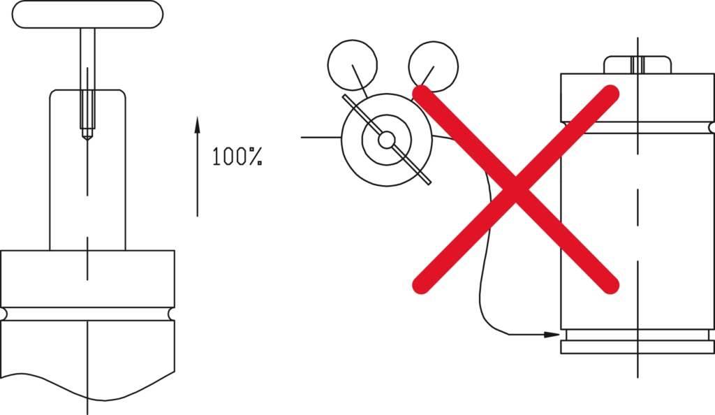
• Never fill a gas spring when the rod is not fully extended.
Thread the T-handle 082078/000 (M8) or (M6) into the rod end and depress the valve stem with the Valve Bleed Tool, then pull the guiding ring up until it is seated firmly against the retaining ring.
Technical data
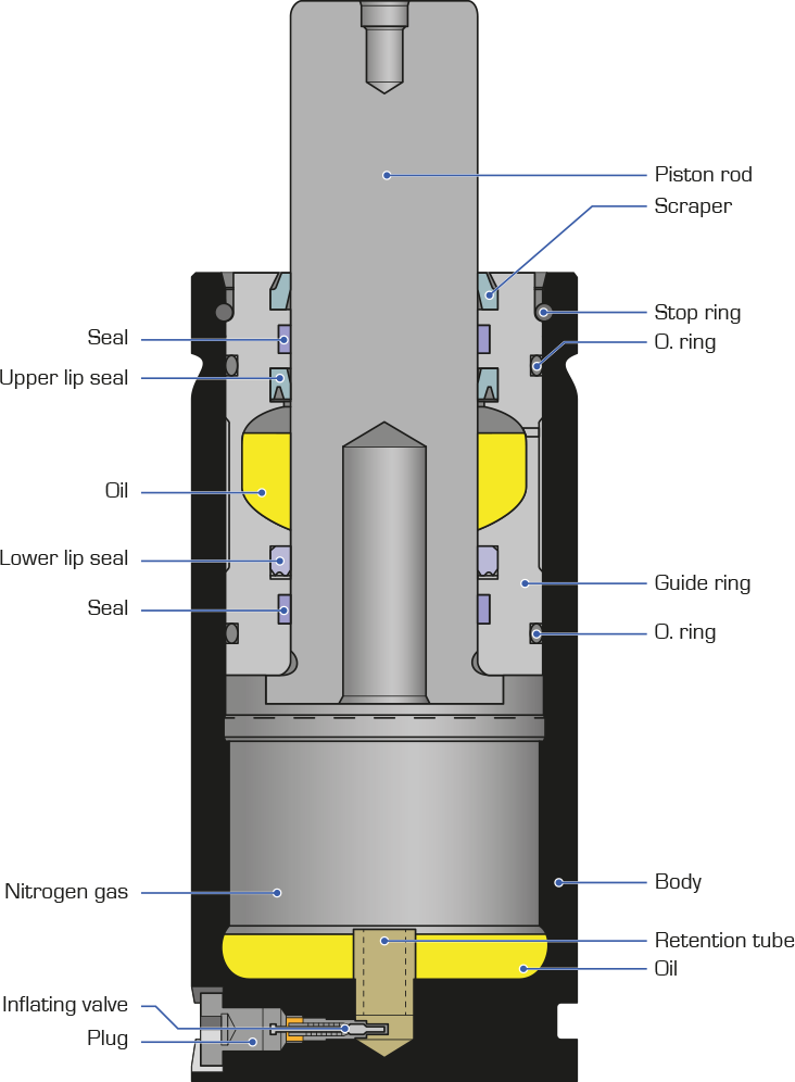
Structure of Quiri ISO gas spring
Gas spring force calculation
The force of a Gas spring depends on the Nitrogen pressure and the working surface.
F kgf= P bar x S cm2, with S=(Pi.d2/4), Pi=3.14
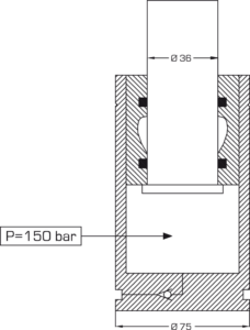
Piston sealed gas spring
• RG 1500 ISO
d = 36 mm = 3.6 cm
P = inflating pressure = 150 bar
S = Pi /4 x 3.62 = 10.17 cm2
F1 = 150 x 10.17 = 1525 kgf
Unit conversion :
10 bar = 1 MPa
1 kgf = 9.81 N
1 daN = 10 N = 1.02 kgf
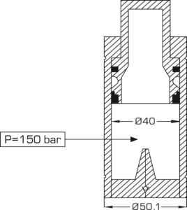
Bore sealed gas spring : Super compact
To calculate the working surface we must take the bore diameter – see the position of the seals.
• RGC 1800 Super compact
d = 40 mm = 4 cm
P = 150 bar
S = Pi/4 x 42 = 12.56 cm2
F1 = 150 x 12.56 = 1884 kgf
Pressure / force build-up K
As the piston rod enters the cylinder body, the inner gas volume will be reduced. Nitrogen, like all gas is compressible, therefore the pressure inside the body will increase.
NB : In this calculation we do not consider temperature change.
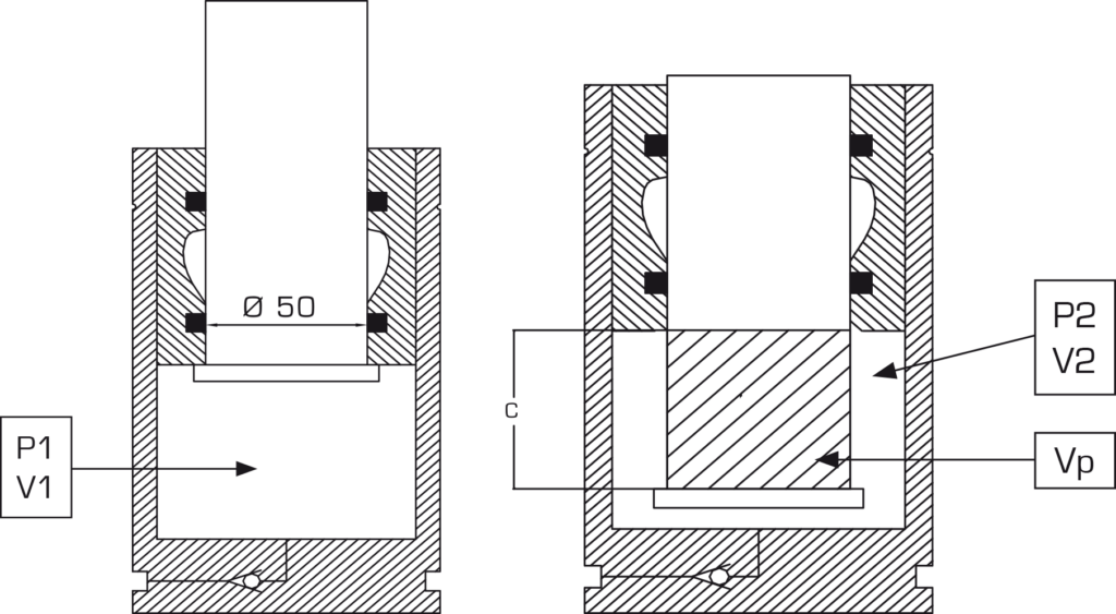
BOYLE-MARIOTTE law
P1 x V1 = P2 x V2
=> P2 / P1 = V1 / V2, P2 / P1 = K is called the pressure build-up.

F1 = P1 x S and F2 = P2 x S => F2 = (P2 / P1) x F1 = (V1 / V2) x F1 = K x F1
V2 is the initial volume minus the volume of the piston rod entering the cylinder body :
V2 = V1 – Vp with Vp = surface x course = (Pi/4 x d2) x C
• RG 3000 ISO C50
d = 50 mm, used stroke C = 40 mm = 4 cm, V1 = 356 cm3
Vp = Pi/4 x d2 x C = Pi/4 x 52 x 4 = 78.54 cm3
V2 = V1 – Vp = 356 – 78.54 = 277.47 cm3
K = P2 / P1 = V1 / V2 = 356 / 277.47 = 1.25
F = K x F1 = 1.25 x 2950 = 3687 kgf at 40 mm stroke
Temperature influence on pressure
In real conditions, gas springs produce heat due to the seals friction. This is called JOULES effect. Gas springs maximum operating temperature is 70°C. Nitrogen pressure will increase with the temperature.
CHARLES law :
Pinitial / Tinitial = Pfinal / Tfinal
=> Pf = Pi x Tf/Ti ; T = temperatures in °Kelvin (°C + 273)
• RG 3000 force is 2950 kgf and initial pressure Pi = 150 bar at 20 °C
A 70 °C : Pf = 150 x (70+273)/(20+273) = 150 x 1.17 = 175 bar
The pressure increase is 17 %, we can calculate the force at 70 °C
Initial force 2950 kgf at 20 °C
F1 à 70 °C = 2950 x 1.17 = 3451 kgf
Polytropic effect
The speed of gas compression/depression will also increase/decrease the gas temperature and therefore the pressure. This is called the polytropic effect. We have seen that for a given stroke we have :
F2 = F1 x K, using Boyle-Mariotte law
K is the isothermal pressure build-up coefficient
If we introduce the influence of the speed of gas compression it will become :
F2 = F1 x Kn
n is called the polytropic exponent and varies with the initial pressure and the speed of the gas compression.
For standard press die applications n=1.6
• RG 3000-50
Course utile égale à 40 mm
K à 40 mm = 1.25
n = 1.6
F2 = F1 x 1.251.6 = F1 x 1.43 = 4218 kgf
All the data in our catalog are isothermal pressure and forces.
Advantage of gas springs vs. coil springs
More force in less space
One Super compact RGC 4700 C25 (body ø 75 mm, stroke 25 mm) against 14 Coil springs, extra heavy load, ø 50 mm with 25 mm pre-loading.

Benefits :
• Reduction of required surface area, 44 cm2 for the cylinder against 274 cm2 for the coil springs.
• Reduction of height, only 135 mm for the cylinder against 280 mm for the coil springs.
• Reduction of volume required, only 596 cm3 for the cylinder against 7963 cm3 for the springs.
• Reduction in the number of retaining device to pre-load, guide and seat. None for the cylinder against 14 for the springs.
• Reduction of cost
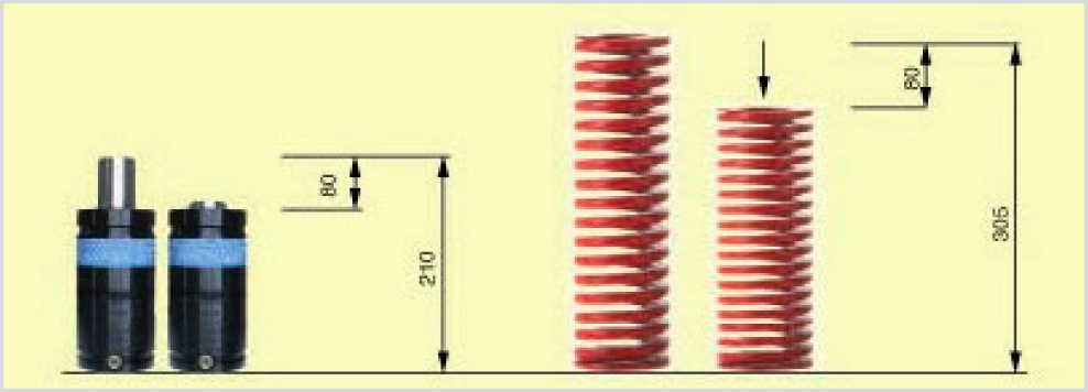
Same working deflection in less height
One RGH 500-80 (low profile gas springs ø 45 mm stroke 80 mm, total height 210 mm and a final force 636KgF) against 1 coil spring (medium load spring, ø 63 mm, working stroke 80 mm as 25% of length for long life, total height of 305 mm and a final force 518 KgF).
Benefits :
• Considerable height reduction for the same working deflection and force.
• Compact die construction.
• Reduction of cost
Large force on contact
All nitrogen gas springs provide high and known initial forces on contact from 22.5daN (for the RG19 – 22.5 with a body ø 19mm) up to 18300daN (for the RGC 18300 with a body ø 150mm). Any mechanical wire compression spring requires a pre-load to obtain such initial forces.
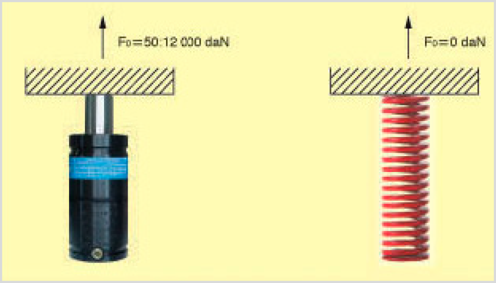
Benefits :
• No pre-load.
• Easier and quicker fitting.
• Reduction of cost
Balanced and controlled forces
Nitrogen cylinders linked with hoses will guarantee a balanced system ensuring the same force in each cylinder. This is not possible by using coil springs since their working characteristics are never exactly the same.
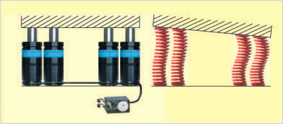
Benefits :
• Always the same force on each contact point.
• Forces may be setup at needed value.
• System may be continually monitored for pressure.
• Reduction of cost
Result :
• Constant production conditions of piece parts.
• Longer life for punches and tools.
Gas Spring and Pressure Equipment Directive 2014/68/EU
1] Goals and concerned appliances :
The objective of this directive is to ensure the safety of pressurized devices at all stages of production (design, manufacturing, traceability of materials, tests and marking). This directive concerns every pressure equipment (steam generators, pressurized tanks, pipings, hydraulic cylinders, etc.) with a minimal pressure of 0.5 bars above the atmospheric pressure.
2] Application
• The Pressure Equipment Directive 2014/68/EU is the European relevant directive. It replaces the PED 97/23/EC.
• The decree 2015-799 of 01/07/15 is the transposition of this directive in French law.
• The Ministerial Order of 15/03/2000 defines the operating conditions of the pressure equipment in France.
• This Directive concerns only equipments used in the European Union.
3] Categories and obligations
• PsV < 50
Risk category: Article 4§3
CE marking: None
Obligations for manufacturer: Manufacturing according state of the art
Obligations for user: None
• 50 < PsV < 200
Risk category: Cat. I module A
CE marking: Yes
Obligations for manufacturer: Manufacturing in accordance with the Directive CE Conformity Certificate
Obligations for user: None
• 200 < PsV < 1000
Risk category: Cat. II module D1
CE marking: Yes + identification number of control agency
Obligations for manufacturer:
– Manufacturing in accordance with the Directive CE
– Conformity Certificate Unitary
– Hydraulic testing of equipment under pressure
Obligations for user:
– Periodical visual inspection every 40 months (MO 15/03/2000 art. 10§3)
– Periodical requalification every 10 years (MO 15/03/2000 art. 22§1)
– Requalification in case of repair (MO 15/03/2000 art. 28 & 30)
IMPORTANT : non-exhaustive information note, we invite you to consult the current texts.