Link clamp cylinders Guide
Definition
General
Link clamp cylinders allow the working area to be cleared, thus facilitating workpiece loading operations.
These clamps are designed for automated systems, and reduce non-productive time. Link clamp cylinders allow the working area to be cleared, thus facilitating workpiece loading operations.
These clamps are designed for automated systems, and reduce non-productive time.
Construction
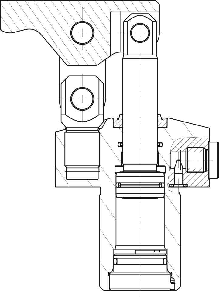
• all parts are made of treated high-strength steel.
• rod treated to prevent seizing and corrosion.
• the body is protected by anti-corrosion treatment.
Location
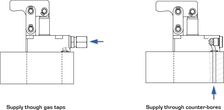
Link clamp cylinders may be supplied by external piping or flanged to the tooling via drilled channels.
Benefits
• short cycle times
• use at low or high pressure
• compact assembly
• wide range with 8 models
• no parasite force
• metal scraper as an option
Important recommendations
Clamp determination
The maximum clamping forces are stated with the max service pressure and a standard flange.
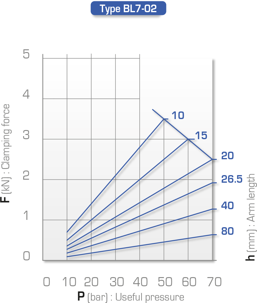
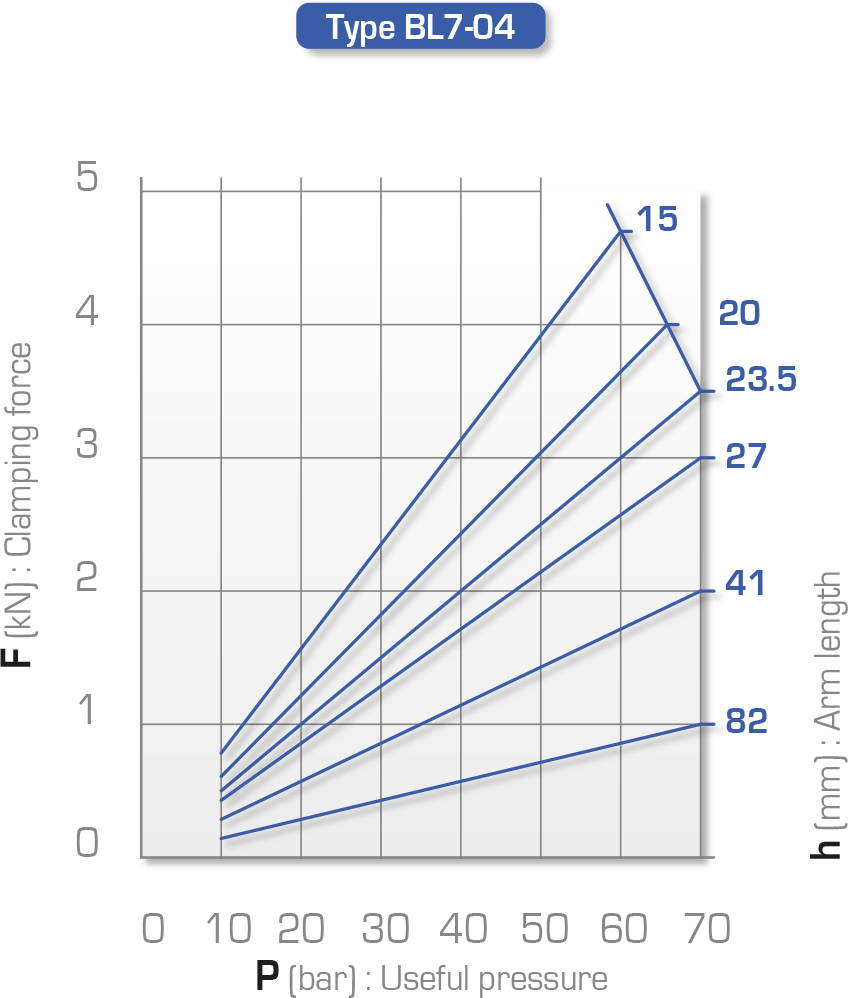
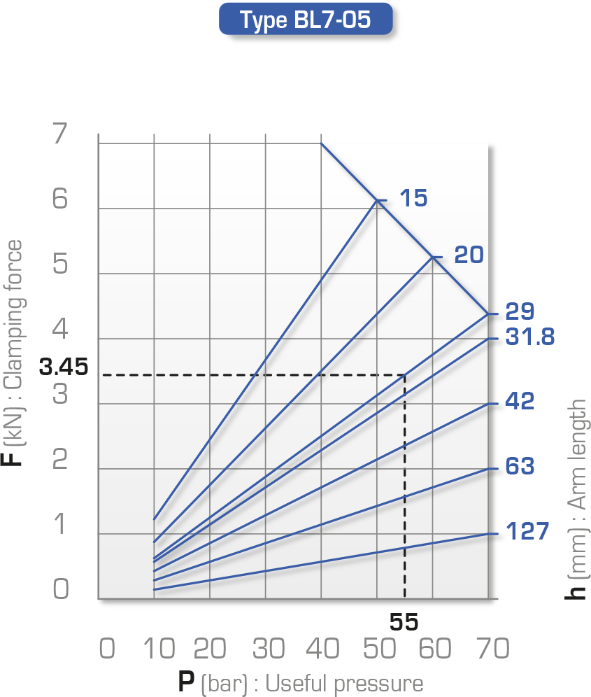
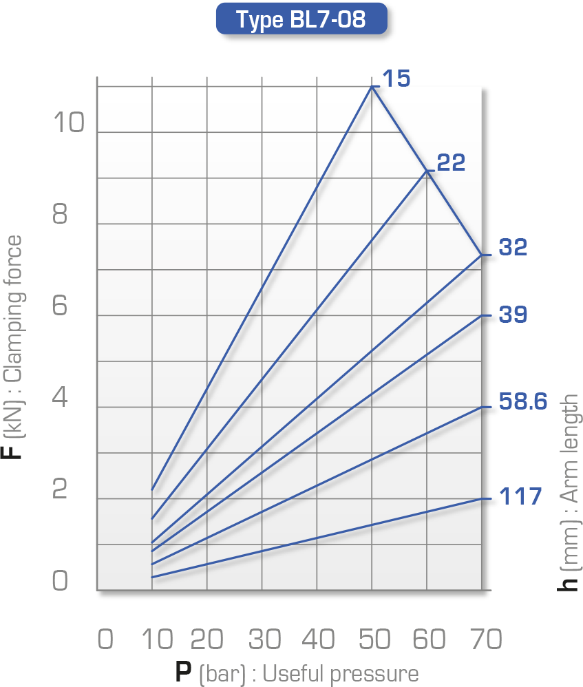
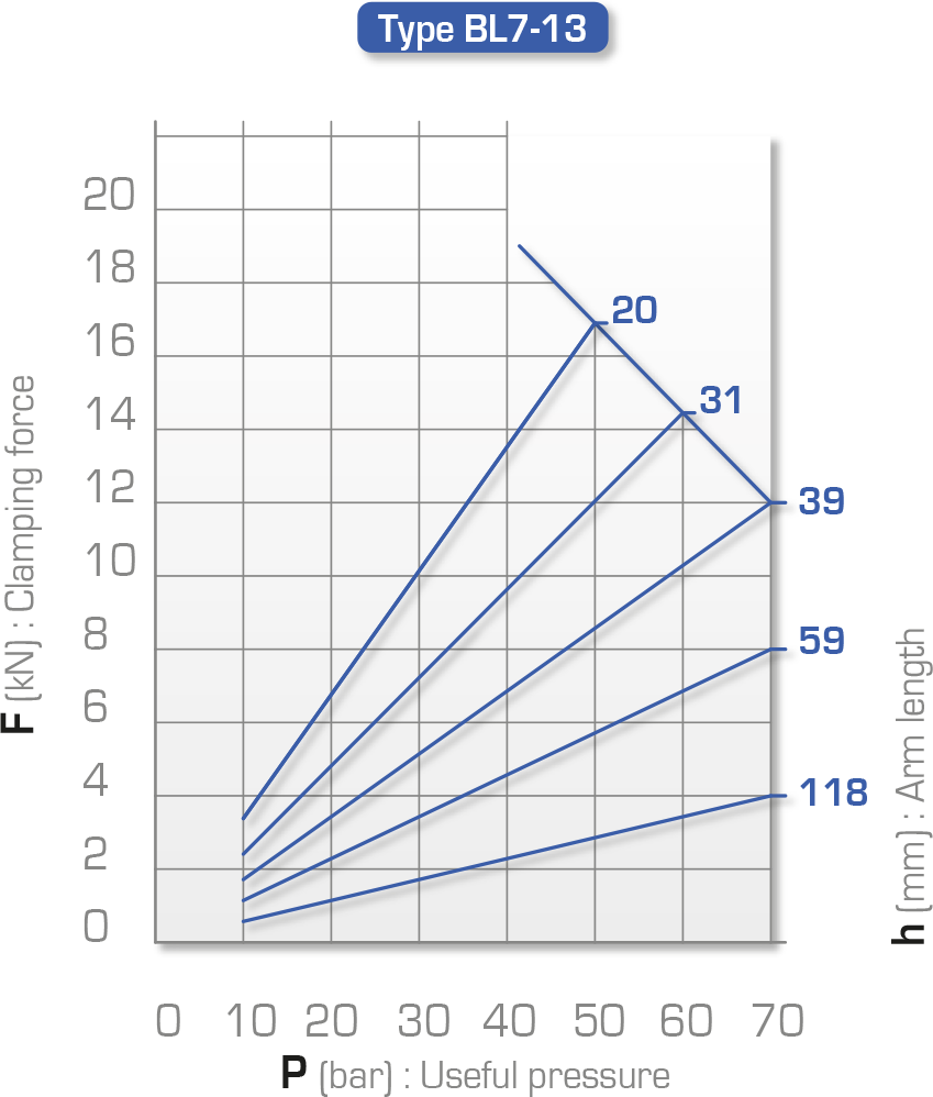
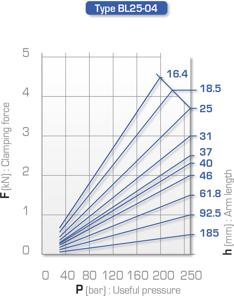
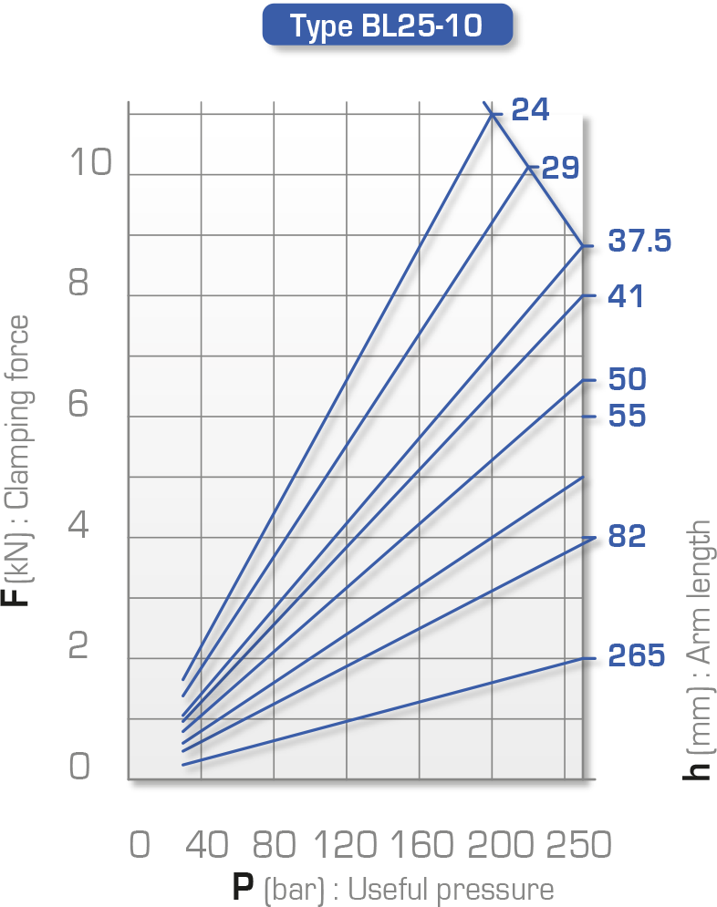
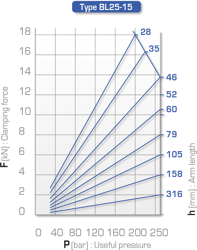
The clamping force reduces in proportion with the arm length: see the calculation formula on pages96 to 99 and the charts on page 95
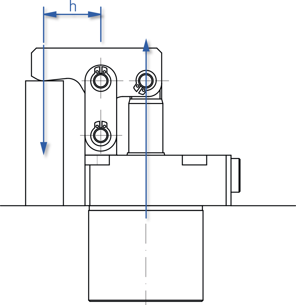
The two axes and the clamping point must be lined up and perpendicular with the axis of the clamp rod, to avoid all parasite forces.
Example of use of charts
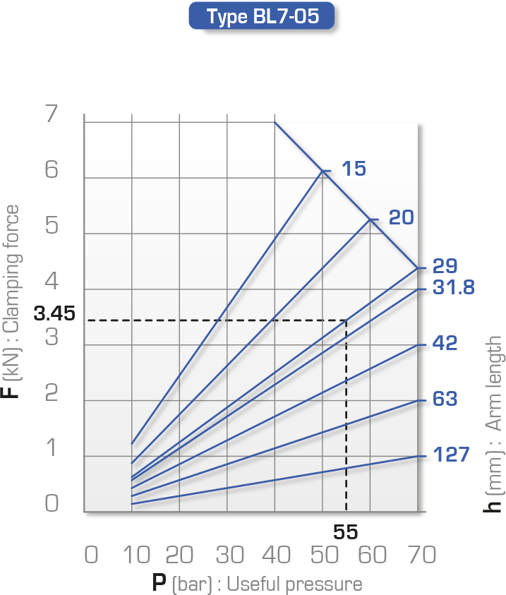
The chart opposite makes it possible to determine the clamping force developed by a clamp depending on the service pressure and the distance h between the centre line of the rod and the clamping point.
For example, the clamping force developed by a BL7-05 clamp at 55 bar with a standard arm (h=29 mm) is 3.45 kN.
The clamping force can also be determined by calculating it: see the formula on pages 96 to 99
Operating pressure
• Minimum : 30 bar
• Maximum: 70 or 250 bar depending on the model
Maximum temperatures
• 70°C
• please enquire for temperatures above 70°C
Important recommendations
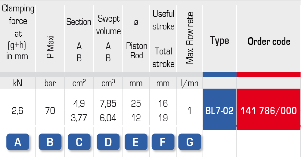
A – This value provides a rough idea of the clamp to select.
B – Service pressure according to the range, 70 or 250 bar
C – Active surface during clamping (A) and release (B)
D – This is the volume of oil displaced over the total travel range
E – The rod has an end with a fastening pin for the clamping flange
F – The difference between the useful and total travel is a safety capacity. Use beyond the useful travel may set the clamp internally at the stop, without effective clamping
G – The recommended maximum flow rate depends on the size of the clamp. The flow rate must be multiplied by the number of clamps operating at the same time.
Characteristics
CAUTION
The table below is provided for guidance only.
To determine actual forces, use the charts on page 95.
| A = clamping
B = release |
Units | BL 7-02 | BL 7-04 | BL 7-05 | BL 7-08 | BL 7-13 | BL 25-04 | BL 25-10 | BL 25-15 | |
| Section | A | cm2 | 4,09 | 7,06 | 9,62 | 15,2 | 24,63 | 2,01 | 4,9 | 8,04 |
| B | 3,77 | 5,53 | 8,08 | 13,19 | 20,82 | 0,87 | 2,36 | 3,13 | ||
| Swept volume | A | cm3 | 7,85 | 12,72 | 20,02 | 34,97 | 71,42 | 4,02 | 14,23 | 27,34 |
| B | 6,04 | 9,95 | 16,97 | 30,34 | 60,4 | 1,76 | 8,72 | 13,56 | ||
| Flow rate | max | l / mn | 1 | 1,5 | 2,4 | 4,5 | 9 | 0,45 | 1 | 1,5 |
| Cycle time | A | s | 0,47 | 0,5 | 0,5 | 0,46 | 0,47 | 0,53 | 0,8 | 1 |
| B | 0,36 | 0,39 | 0,42 | 0,4 | 0,4 | 0,23 | 0,52 | 0,54 | ||
| Clamping travel | Useful | mm | 16 | 18 | 21 | 23 | 29 | 20 | 29 | 34 |
| Total | 19 | 21 | 24 | 26 | 32 | 23 | 32 | 37 | ||
Charts
