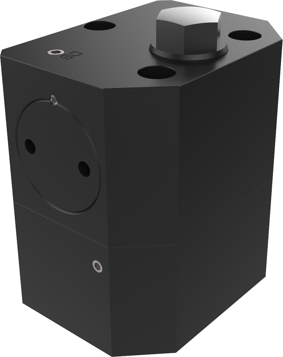
Single-acting with spring return
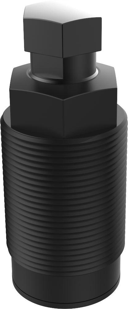
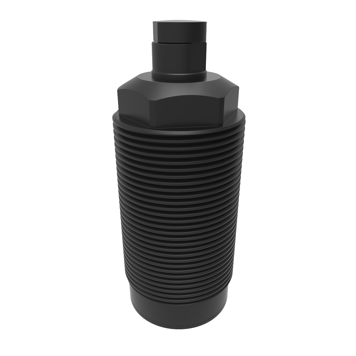
Work support with cartridge – 300 bar AVC
Cartridge type
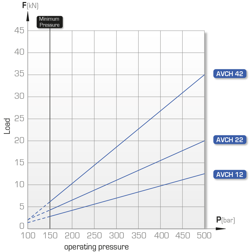
Locking force at 300 bar: 5 to 20 kN
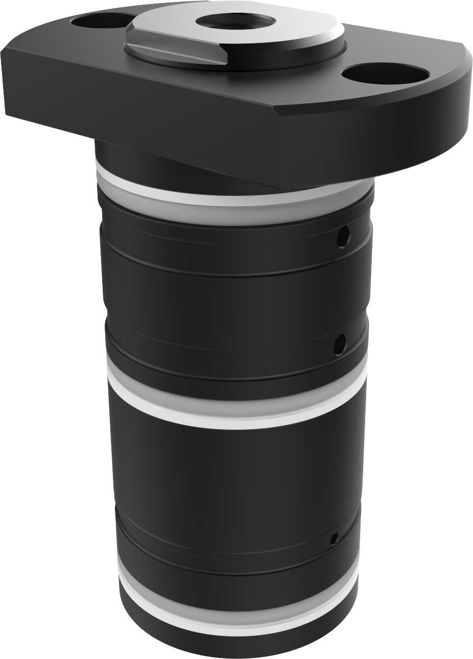
Hydraulic supports are designed to support the workpieces in a specific plane and eliminate vibration during machining.
Support with single hydraulic supply port for extension and locking of the rod.
For the operating principle, consult the guide.
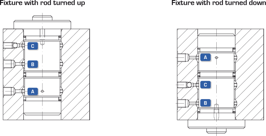
Examples of fixtures, see at the bottom of the page.
• fastened by upper flange
• direct supply through manifold block
• stainless steel return spring
For operating pressure values below
150 bar, please enquire.
Special models can be made upon request.
IMPORTANT
The bleeder must be located at the highest point in the fixture.
In order to allow spring return, the counter pressure must not exceed 2 bar
Max flow rate: 1.5 l/min
| Contact force | ||
| Type
|
Rod retracted Max. |
Rod extended Min. |
| N | N | |
| AVC 11 R | 36 | 8 |
| AVC 21 R | 52 | 8 |
| AVC 41 R | 100 | 45 |
NAMES:
Rod extended at rest = Contact force generated by a spring: AVC__R
Rod free = Contact force generated by compressed air : AVC__A
Rod retracted at rest = Contact force generated by compressed air and return spring: AVC__AR
| Locking force
at 300 bar |
Locking force
at 150 bar |
Elastic collapse at 500 bar | Travel | Rod
Ø |
Type | Reference | ||||||||||||||||
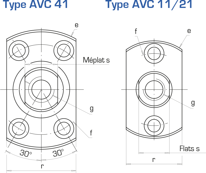
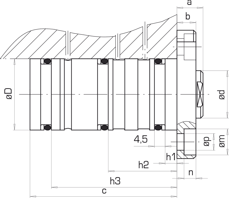
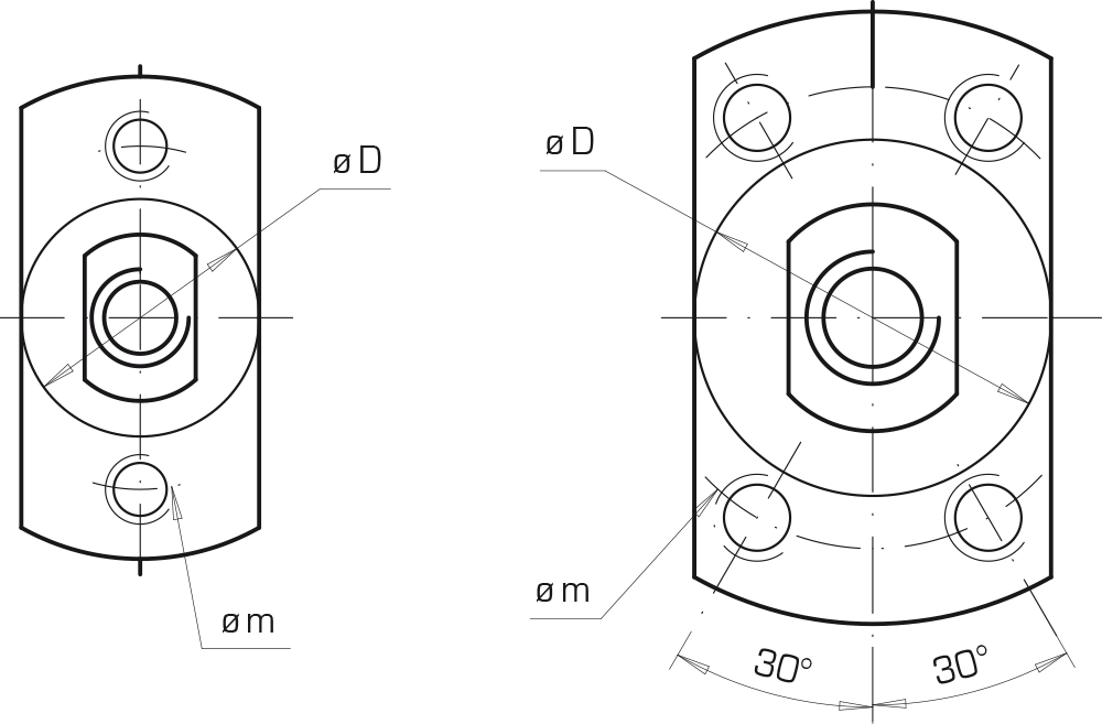
| D | g | a | b | c | e | f | h1 | h2 | h3 | p | m | n | r | s | ||||||||
| kN | kN | µm/kN | mm | mm | mm | mm | mm | mm | mm | mm | mm | mm | mm | mm | mm | mm | mm | mm | ||||
| 5 | 2 | 4.5 | 12 | 20 | AVC 11 R | 751 042/000 | 30 | M12 lg. 15 | 11 | 8 | 62 | 54 | 40 | 5 | 29 | 53 | 7 | 11 | 5 | 31 | 17 | 3D |
| AVC 11 A | 751 042/100 | |||||||||||||||||||||
| AVC 11 AR | 751 042/200 | |||||||||||||||||||||
| 10 | 3.7 | 3 | 18 | 30 | AVC 21 R | 751 046/000 | 40 | M12 lg. 22 | 13 | 10 | 80 | 65 | 50 | 5 | 35 | 71 | 7 | 11 | 6.8 | 42 | 24 | 3D |
| AVC 21 A | 751 046/100 | |||||||||||||||||||||
| AVC 21 AR | 751 046/200 | |||||||||||||||||||||
| 20 | 6.3 | 2 | 20 | 40 | AVC 41 R | 751 081/000 | 50 | M12 lg. 12 | 14 | 10 | 90 | 75 | 60 | 5 | 42 | 79.5 | 7 | 11 | 6.8 | 52 | 32 | 3D |
| AVC 41 A | 751 081/100 | |||||||||||||||||||||
| AVC 41 R | 751 081/200 | |||||||||||||||||||||
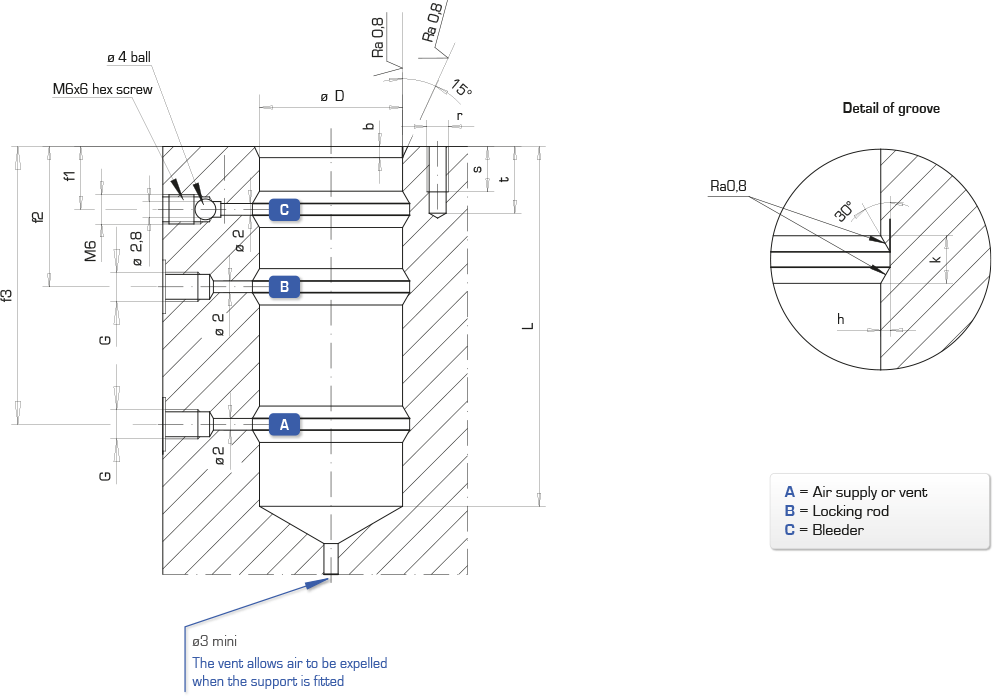
Machining dimension
IMPORTANT NOTE:
The bleeder must always be located at the highest point in the fixture.
Bleed at low pressure (below 20 bar)
General tolerances Js13
Round off and polish sharp angles
| Type
|
øD
H7 |
b
|
L
min |
f1
|
f2
|
f3
|
G
|
h
min |
k
|
m
|
r
|
s
|
t
|
| mm | mm | mm | mm | mm | mm | mm | mm | mm | mm | mm | mm | ||
| AVC 11 | 30 | 3 | 64 | 13 | 24 | 46 | G1/4″ | 0,5 | 3 | 40 | M6 | 10 | 12 |
| AVC 21 | 40 | 3 | 82 | 14 | 30 | 63 | G1/4″ | 1 | 4 | 50 | M6 | 10 | 12 |
| AVC 41 | 50 | 3 | 92 | 13,5 | 30 | 75 | G1/4″ | 1 | 5 | 60 | M6 | 10 | 12 |
