
Linear cylinders
Other products
Access Linear cylinders 's products
Access selection
Back to Hydraulic Clamping Systems
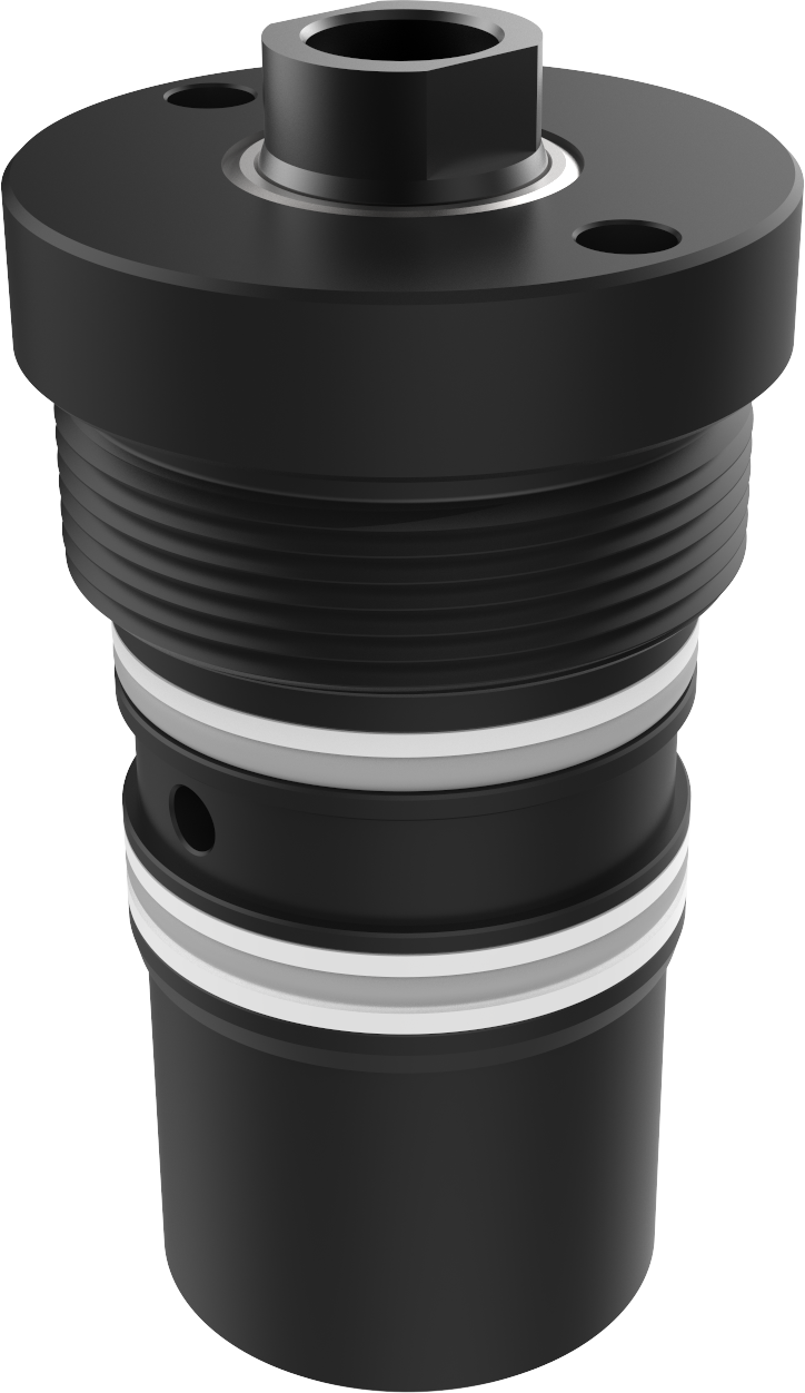
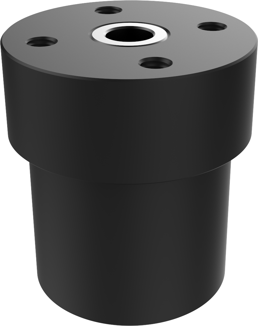
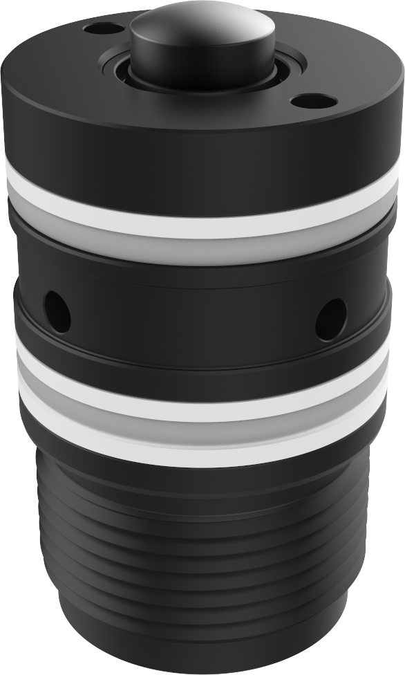
Snap-in clamping head CSM
Single-acting - for T groove
Clamping force at 400 bar 19 kN to 78 kN
The snap-in hydraulic unit is designed for small and medium-sized presses up to approximately 700 tonnes. These units are suitable for clamping tools at the top and bottom and require tools with straight clamping edges.
The snap-in unit is inserted manually in the T groove of the machine. This flexible method of use makes it possible to clamp different sizes of tools. When used along with intermediate plates, the snap-in unit is also applicable to different clamping edge thicknesses.
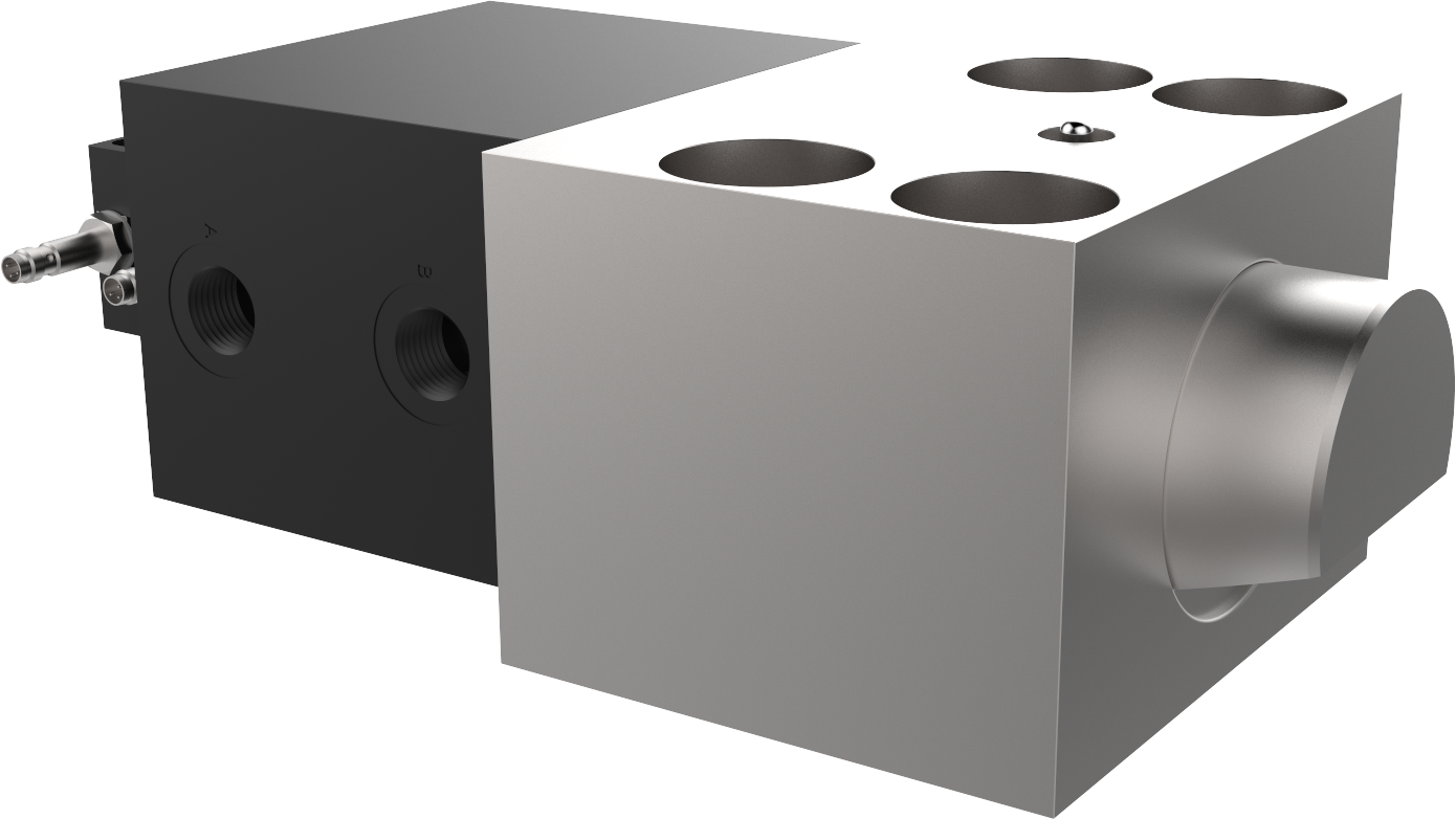
A single-acting hydraulic clamp with a return spring transmits the required clamping force to the tool. The release process is carried out after the hydraulic valve is switched by means of a return spring. The hydraulic clamp directly generates the required clamping force. Hydraulic pressure must be maintained during the entire clamping time.
• ideal power transmission
• Clamping force 19 kN to 78 kN
• compact design
• easy installation
• suitable for the tolerances of large clamping edges
• maximum operating temperature 80 °C
• max. service pressure 400 bar
The clamping thickness range of the clamping element is designed to suffice for most applications. If the clamping thickness is still insufficient, you can increase it by using intermediate plates.
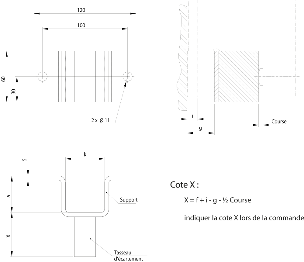
Dimension f is calculated using the formula:
½ the travel range
+ edge height
+ height of T groove

Clamping force: The force with which the tool/mould is clamped against the support.
Functional dimension f(mm) to specify with the order, for example: M 546-2-032-065 (f=65mm) or CSM-032-1-065 (f=65mm)
| T groove according to standard DIN 650
|
Rod
øD |
Travel
max |
Pressure
max |
Clamping force
max |
Type | Reference | |||||||||||||||
| b
|
c
|
ød1
|
e
|
e1
|
g
|
h
|
i
|
k
h9
|
L
|
L1
|
m
|
f
min
|
f
max
|
p
|
|||||||
| mm | mm | mm | bar | kN | mm | mm | mm | mm | mm | mm | mm | mm | mm | mm | mm | mm | mm | mm | mm | ||
| 18 | 25 | 8 | 400 | 19.2 | CSM – 025 – 1 – f | M 546-1-025-f | 65 | 40 | 15 | 23 | 32 | 24 | 25 | 10 | 18 | 95 | 77 | 28 | 42 | 90 | G1/4 |
| 22 | 25 | 8 | 400 | 19.2 | CSM – 025 – 2 – f | M 546-2-025-f | 65 | 40 | 15 | 23 | 32 | 32 | 30 | 14 | 22 | 95 | 77 | 35 | 50 | 106 | G1/4 |
| 22 | 32 | 8 | 400 | 32 | CSM – 032 – 1 – f | M 546-2-032-f | 65 | 47 | 15 | 28 | 41 | 32 | 30 | 14 | 22 | 104 | 81 | 35 | 50 | 106 | G1/4 |
| 22 | 40 | 8 | 400 | 50 | CSM – 040 – 1 – f | M 546-2-040-f | 65 | 50 | 20 | 31 | 48 | 32 | 30 | 14 | 22 | 111 | 85 | 35 | 50 | 106 | G1/4 |
| 28 | 32 | 8 | 400 | 32 | CSM – 032 – 2 – f | M 546-3-032-f | 65 | 47 | 15 | 28 | 41 | 42 | 37 | 18 | 28 | 104 | 81 | 44 | 55 | 106 | G1/4 |
| 28 | 40 | 8 | 400 | 50 | CSM – 040 – 2 – f | M 546-3-040-f | 65 | 50 | 20 | 31 | 48 | 42 | 37 | 18 | 28 | 111 | 85 | 44 | 55 | 112 | G1/4 |
| 28 | 50 | 12 | 400 | 78 | CSM – 050 – 1 – f | M 546-3-050-f | 80 | 75 | 25 | 38 | 60 | 42 | 37 | 18 | 18 | 132 | 99 | 44 | 60 | 117 | G1/4 |