Swing clamps with helical rotation Guide
Definition of swing clamp
General
Swing clamps allow the working area to be cleared, thus facilitating workpiece loading and unloading operations. These clamps are designed for automated systems, and reduce non-productive time.
Construction
• all parts are made of treated high-strength steel.
• rod treated to prevent seizing and corrosion.
• the body is protected by anti-corrosion treatment.
Benefits
• all our swing clamps have bleeders
• easy removal of clamping arm with 15° taper
• rod with 1:10 taper on request
• repositioning guaranteed thanks to rod indexing
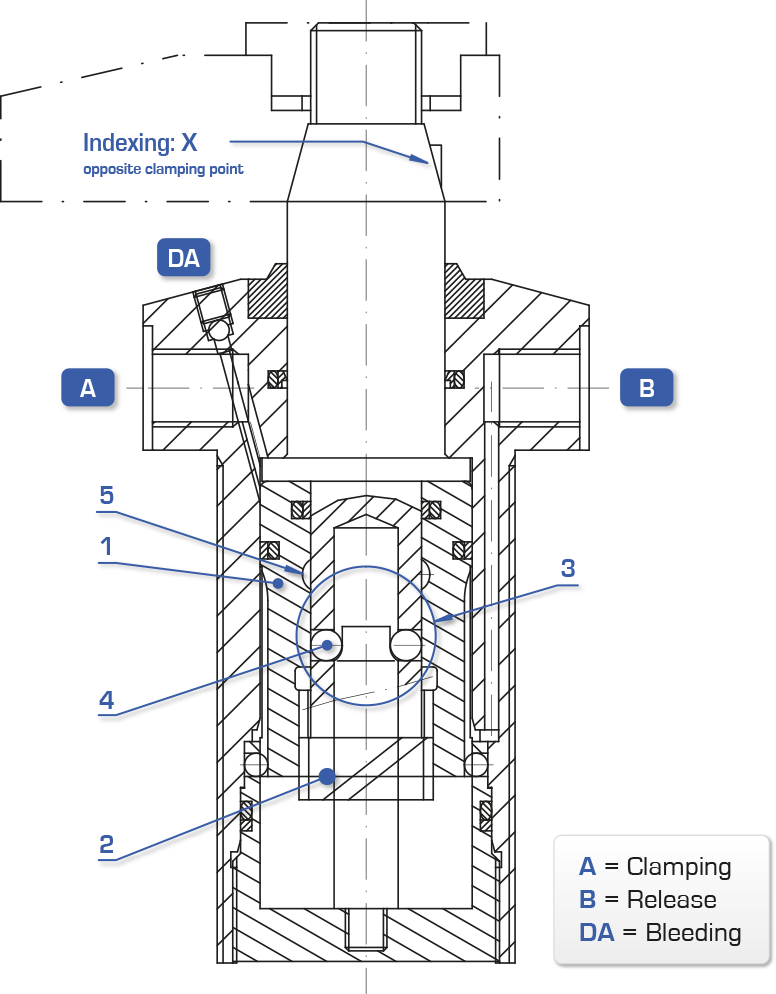
Operation
Clamping phase: Supply from A
When the clamp is put under pressure, the piston rod swings along a helical path, followed by linear clamping travel. The total travel and the linear clamping travel are stated in the technical data sheet specific to each type of clamp
Release phase: Supply from B
Supplying the return port B causes an upward displacement movement of the rod, followed by a helical swing movement to return to the initial position.
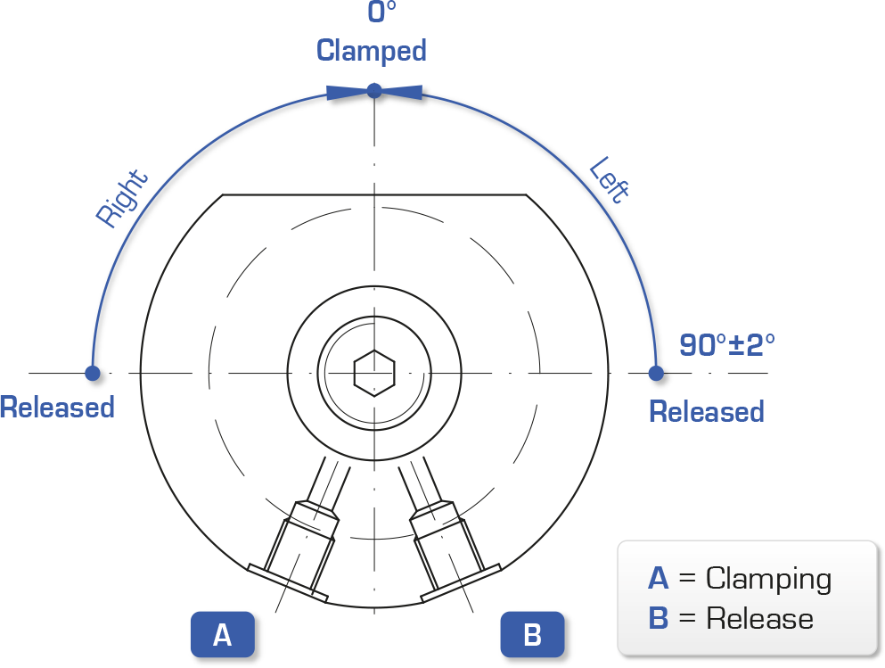
Direction and angle of rotation
The direction of rotation is indicated from the initial released position with the rod extended to the clamped position with the rod retracted, rod viewed from above:
Right = clockwise direction
Left = anticlockwise direction
Standard angle of rotation: 90°, 45°, 60° ± 2°.
Other angles of rotation on request
Clamp determination
The maximum forces are provided for 250 bar pressure. This pressure is only permitted if the shortest of the three standard arms available is used.
Maximum force (and thus maximum pressure) decreases proportionally with the length of the arm: see charts.
Maximum flow rate also decreases with the inertia of the arm; refer to the values indicated in the charts for standard arms. Please enquire if special arms are needed.
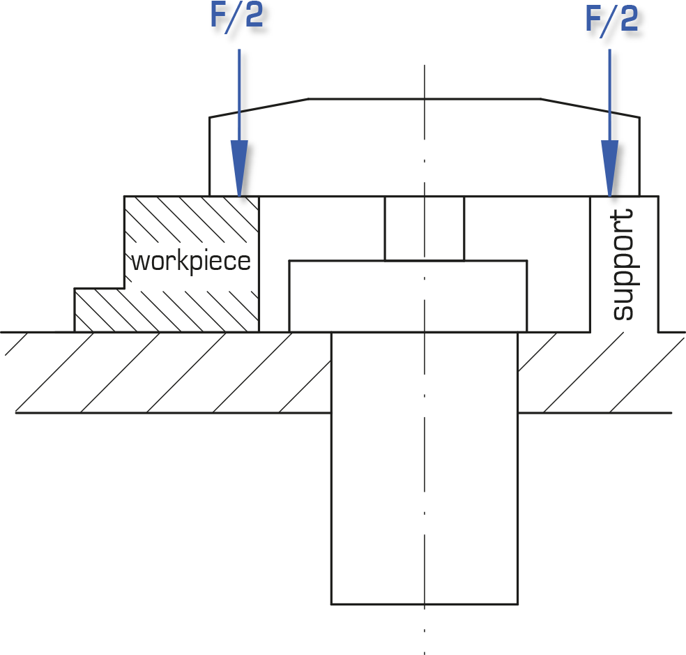
The use of a double symmetrical arm allows operation at 250 bar; forces must then be divided by two and flow rate reduced by half because of inertia.
For example:
For a double arm and maximum force of HL 21:
F/2 = P x S ÷ 2 = 250 x 4.71 ÷ 2 = 5.8 kN
| Maximum pressure with standard arms | |
| Maximum pressure | Type of arm |
| bar | |
| 250 | short arm BC |
| 175 | medium arm BM |
| 125 | long arm BL |
Min operating pressure: 30 bar
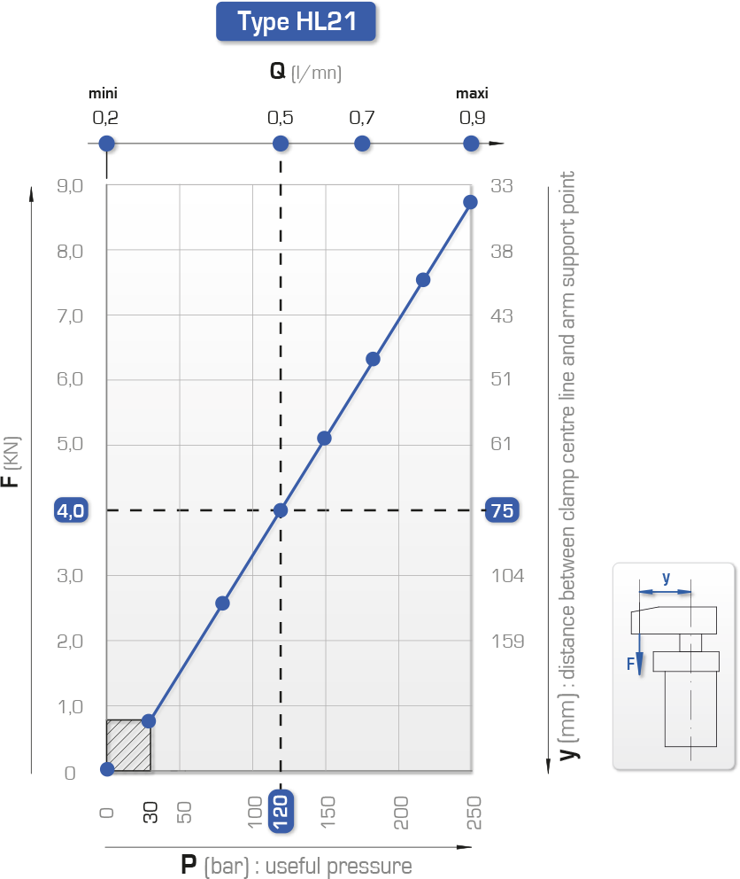
Example of use of diagrams
The diagram opposite allows you to determine the maximum force developed by the clamp and the maximum pressure depending on the type of arm used: BC, BM, or BL. They also indicate the limit values of flow rate Q.
The maximum force developed by a clamp of the HL21 type with a BL 21 arm that is 75 mm long is 4 kN at 120 bar with a maximum flow rate Q of 0.5l/min per clamp.
To determine special arm specifications, use the charts on HL.
Important recommendations – Characteristics
Operating pressure
minimum: 30 bar
• maximum: 250 bar with short arms (see charts)
Maximum temperatures
• 70°C
• please enquire for temperatures above 70°C
Important recommendations
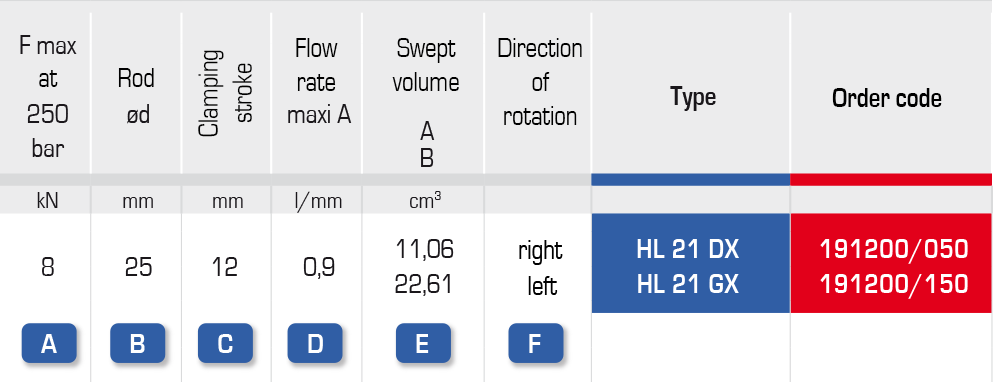
A – This value provides a rough idea of the clamp to select. Always refer to the diagram of forces present in the clamp drawings for P5 type or on HFL5 for HL21 or HL31 in order to define the maximum pressure and force depending on the arm length “y”.
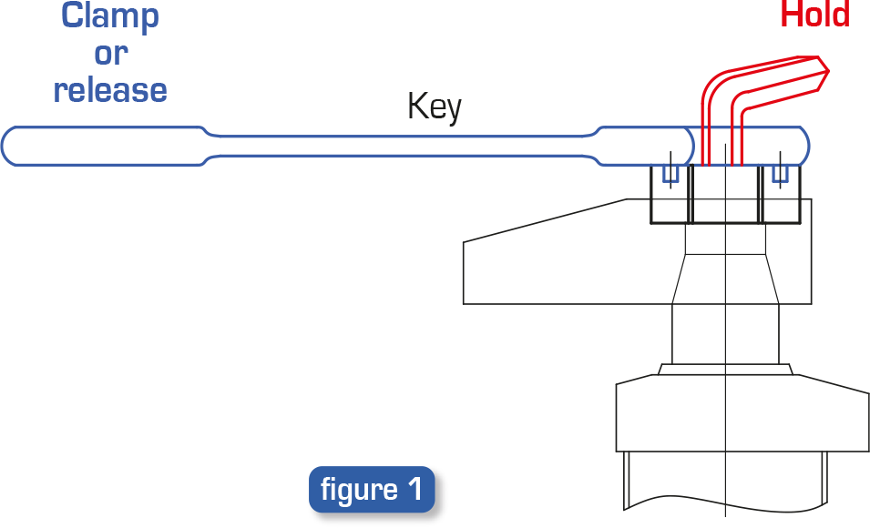
B – The rod has a tapered end and is threaded for fastening the clamping arm with braking. When locking the nut, the rod must absolutely be prevented from rotating in order not to transmit the tightening torque to the internal mechanism.
There are two ways of doing this:
• hold the rod with a hexagon spanner (see figure 1 )
• hold the arm in a vice
C – The indicated value corresponds to the maximum clamping travel of the clamp. For clamping a workpiece, the useful travel is between the minimum and maximum values indicated in the table of characteristics below.
D – The maximum recommended flow rate will vary with the type of clamp and the inertia of the clamping arm. Refer to the table and if possible, provide a nozzle or adjustable restrictor in the distribution circuit. The flow rate must be multiplied by the number of clamps operating at the same time: ensure that minimum flow rates are observed. The flow rate may be limited by using nozzles.
E – This is the volume of oil displaced during over the total travel range.
F – Direction of rotation of the rod from the released position to the clamped position. Rod seen from above
Characteristics
See table opposite.
CAUTION
The table opposite is provided for guidance.
To determine the actual forces, please use the charts provided on HL, which take account of efficiency.
| A = Clamping
B = Release |
Units | P5 | HL 12 | HL 21 | HL 31 | |
| Section | A | cm2 | 0.98 | 3.01 | 4.71 | 9.45 |
| B | 1.77 | 6.15 | 9.62 | 19.63 | ||
| Swept volume | A | cm3 | 1.67 | 6.9 | 11.06 | 26.95 |
| B | 3 | 14.1 | 22.61 | 55.94 | ||
| Max flow rate | max | l/min | 0.2 | 0.6 | 0.9 | 2 |
| Cycle time | A | s | 0.5 | 0.7 | 0.74 | 0.8 |
| B | 1.1 | 1.4 | 1.5 | 1.6 | ||
| Linear travel | max | mm | 4 | 10 | 10 | 13 |
| min | 1 | 3 | 3 | 3 | ||
| Total travel | mm | 17 | 23 | 23.5 | 28.5 | |