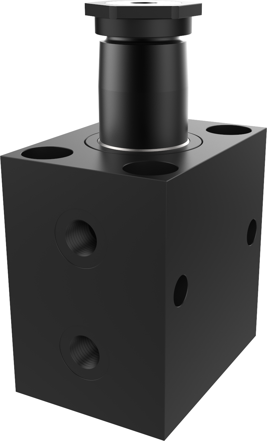
Supply through counter-bores under the flange ring

Swing clamps with helical rotation
Other products
How to choose a Swing clamps with helical rotation Guide ?
Access Swing clamps with helical rotation 's products
Access selection
Back to Hydraulic Clamping Systems
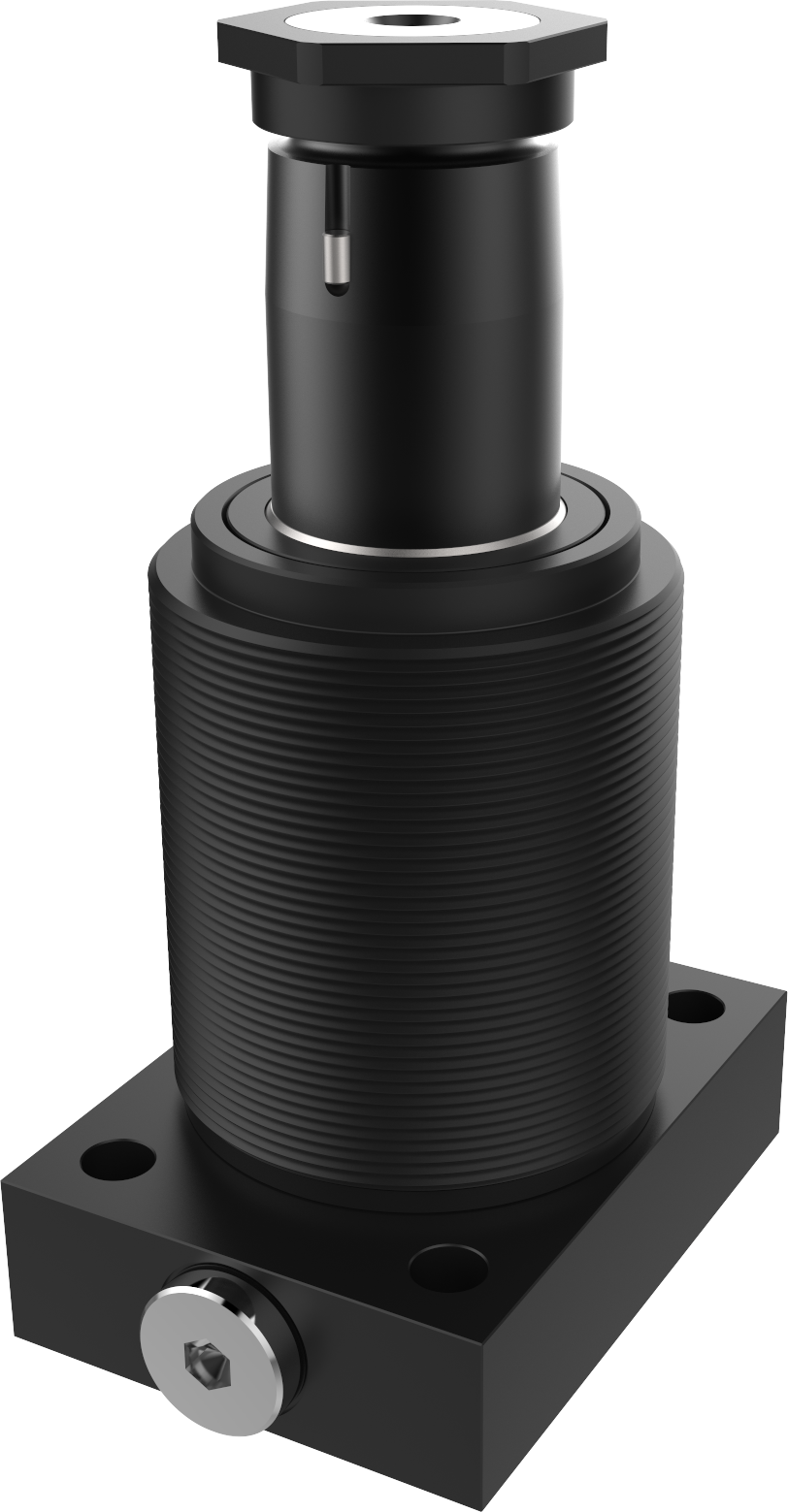
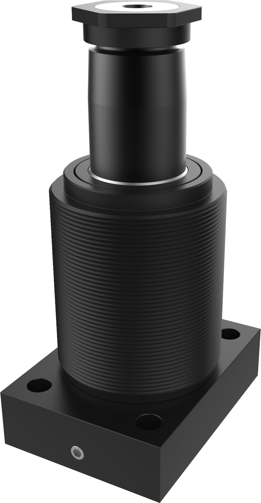
Double-acting swing clamp – 250 bar – Supplied through counter-bores under the head HL
Double-acting - with rotation travel
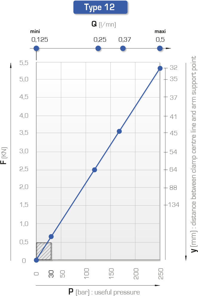
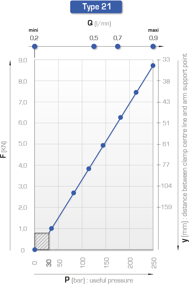
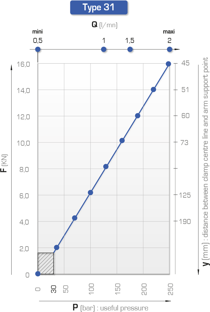
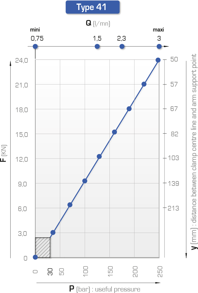
Force at 250 bar: 5 to 24 kN

• total travel = rotation travel + clamping travel
• right or left helical rotation, 90°±2°
• bleeder near clamping (HL12, HL21, HL 31 & HL 41)
• additional bleeder near release (HL31 & HL 41)
• rod indexing
• maximum service pressure: 250 bar
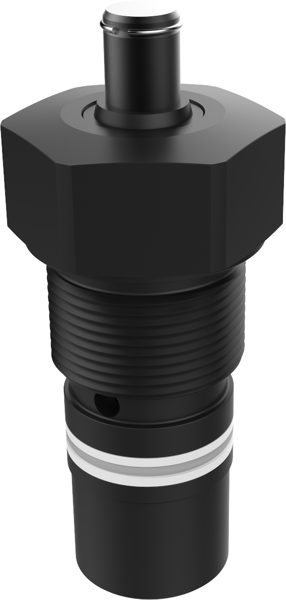
STANDARD WITH NO INDEXING
• different travel ranges on request
• choice of rotation angle in 5° increments (please specify with the order)
• metal scraper (please specify with the order)
• optional indexing (please specify with the order)
STANDARD WITH INDEXING
• different travel ranges on request
• choice of rotation angle in 5° increments (please specify with the order)
• metal scraper (please specify with the order)
• also with no optional indexing (please specify with the order)
Clamps are supplied with O-rings, lock nut and lock washer
(dimensions and tightening torque: see Lock washer for clamp type P11, P21 and Nut for clamp type P31 and P41).
O-rings:
- 5.28 x 1.78 (HL12, HL 21) 90 shore NBR
- 7.65 x 1.78 (HL 31) 90 Shore NBR

Definition of forces depending on clamping arm: see charts at the bottom of the page
Important recommendations: consult the guide
NOT INDEXED: The pin may be removed using a drift punch
| F max
at 250 bar |
Rod
ød |
Travel
of torque |
Travel
total
|
Max flow rate
A |
Swept volume
A B |
Direction
of rotation |
α = 15° (with indexing) | α = 1:10 (without indexing) | |||||||||||||||||||
| Type
|
Reference
|
e1
|
Reference | e2
|
a
|
c
|
øD
|
f
|
h
|
øk1
øk2
|
L
|
L1
|
L2
|
L3
|
m1
|
m2
|
p1
|
p2
|
p3
|
||||||||
| kN | mm | mm | mm | l/min | cm3 | mm | mm | mm | mm | mm | mm | mm | mm | mm | mm | mm | mm | mm | mm | mm | |||||||
| 5 | 20 | 12 | 23 | 0.5 | 6.9 | right | HL 12 DX | 191 217/050 | M14x1.5 | M 625-R-020 | M18x1.5 | 14 | 10 | 45 | 5 | 23 | 68 | 138.5 | 88.5 | 66.5 | 48 | 8.8 | 4 | 6.5 | 10.5 | 8 | 3D |
| 14.1 | left | HL 12 GX | 191 217/150 | M 625-L-020 | 56 | 3D | |||||||||||||||||||||
| 8 | 25 | 12 | 24 | 0.9 | 11.06 | right | HL 21 DX | 191 200/050 | M16x1.5 | M 625-R-025 | M22x1.5 | 16 | 14 | 52 | 6 | 28 | 76 | 146.5 | 89.5 | 63.5 | 53 | 8.8 | 4 | 6.5 | 10.5 | 16 | 3D |
| 22.61 | left | HL 21 GX | 191 200/150 | M 625-L-025 | 63 | 3D | |||||||||||||||||||||
| 8 | 25 | 25 | 37 | 0.9 | 17.42 | right | HL 21 DX C25 | 191 210/050 | M16x1.5 | M 625-R-025-25 | M22x1.5 | 16 | 14 | 52 | 6 | 28 | 76 | 175.5 | 105.5 | 79.5 | 66 | 8.8 | 4 | 6.5 | 10.5 | 16 | 3D |
| 35.59 | left | HL 21 GX C25 | 191 210/150 | M 625-L-025-25 | 63 | 3D | |||||||||||||||||||||
| 16 | 36 | 15 | 29 | 2 | 26.95 | right | HL 31 DX | 192 162/050 | M16x1.5 | M 625-R-036 | M30x1.5 | 18 | 20 | 72 | 10 | 38 | 110 | 176 | 106 | 78 | 60 | 11.1 | 5 | 10.5 | 17 | 11 | 3D |
| 55.94 | left | HL 31 GX | 192 162/150 | M 625-L-036 | 90 | 3D | |||||||||||||||||||||
| 16 | 36 | 25 | 39 | 2 | 36.85 | right | HL 31 DX C25 | 192 181/050 | M24x1.5 | M 625-R-036-25 | M30x1.5 | 18 | 20 | 72 | 10 | 38 | 110 | 201 | 121 | 93 | 70 | 11.1 | 5 | 10.5 | 17 | 11 | 3D |
| 76.55 | left | HL 31 GX C25 | 192 181/150 | M 625-L-036-25 | 90 | 3D | |||||||||||||||||||||
| 24 | 42 | 15 | 22 | 3 | 46.1 | right | HL 41 DX | 192 188/050 | M30x1.5 | M 625-R-042 | M36x1.5 | 20 | 22 | 88 | 10 | 45 | 128 | 202 | 125 | 95 | 65 | 11 | 5 | 10.5 | 17 | 12 | |
| 50.5 | left | HL 41 GX | 192 188/150 | M 625-L-042 | 108 | ||||||||||||||||||||||
| 24 | 42 | 15 | 22 | 3 | 59.93 | right | HL 41 DX C25 | 192 189/050 | M30x1.5 | M 625-R-042-25 | M36x1.5 | 20 | 22 | 88 | 10 | 45 | 128 | 222 | 135 | 105 | 75 | 11 | 5 | 10.5 | 17 | 12 | |
| 77.35 | left | HL 41 GX C25 | 192 189/150 | M 625-L-042-25 | 108 | ||||||||||||||||||||||
Product charts