High-performance cylinders for all industrial applications
350V series double-acting cylinders
DE - 350V

• Wide embedding
• Rod sealing with negative lip seal
• Piston sealing with double-acting seal
• Intermittent operating pressure: 350 bar
• Intensive working : 315 bar
• Maximum speed : 0,5 m/s with standard seals, up to 2 m/s with special seals
• Maximum temperature : 100°C with standard seals, up to 200°C with viton seals. On demand for temperatures < 0°C.
• Choice of two rod diameters per bore, with differential rod for common applications.
• Standardized bore and rod diameters.
• Standardized rod end thread.
• Download 3D CAD models on www.traceparts.com.
• Bore greater than Ø 140
• Other threads k
• Double-rod cylinder
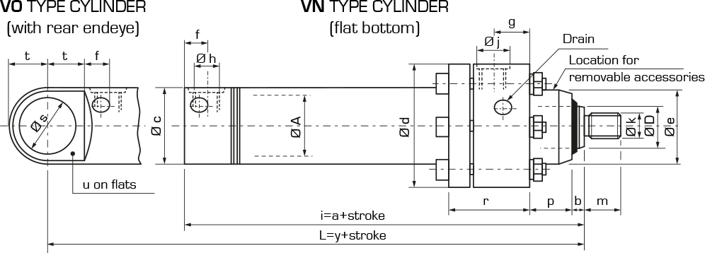
• The rear endeye on VO-type cylinders can be supplied in the following versions :
– Ø S smooth
– with ball joint, snap ring and grease nipple.
Designation
Dimensions
| Bore Ø A | 40 | 50 | 63 | 80 | 100 | 125 | 140 | |
| Rod Ø D | for tension | 22 | 28 | 36 | 45 | 56 | 70 | 80 |
| differential | 28 | 36 | 45 | 56 | 70 | 90 | 100 | |
| a | 167 | 182 | 205 | 238 | 288 | 335 | 370 | |
| b | 5 | 5 | 6 | 6 | 8 | 10 | 10 | |
| Ø c | 50 | 60 | 76 | 96 | 122 | 150 | 170 | |
| Ø d | 80 | 100 | 118 | 140 | 170 | 212 | 236 | |
| Ø e | 48 | 58 | 76 | 92 | 115 | 150 | 166 | |
| f | 15 | 15 | 19 | 19 | 23 | 23 | 26 | |
| g | 20 | 22 | 22 | 30 | 45 | 50 | 55 | |
| h | G 3/8’’ | G 3/8’’ | G 1/2’’ | G 1/2’’ | G3/4’’ | G3/4’’ | G1’’ | |
| i | 24 | 24 | 31 | 31 | 37 | 37 | 43 | |
| k | M18 x 1.5 | M22 x 1.5 | M27 x 2 | M33 x 2 | M42 x 2 | M56 x 2 | M64 x 3 | |
| m | 25 | 30 | 36 | 45 | 56 | 75 | 85 | |
| p | 28 | 32 | 40 | 49 | 56 | 71 | 80 | |
| r | 54 | 60 | 65 | 80 | 105 | 121 | 133 | |
| Ø s | 35 | 42 | 55 | 68 | 90 | 105 | 120 | |
| t | 25 | 30 | 38 | 48 | 61 | 75 | 85 | |
| u | 20 | 24 | 30 | 38 | 50 | 58 | 64 | |
| y | 192 | 212 | 243 | 286 | 349 | 410 | 455 | |
Cylinder selection based on buckling stress
Maximum force : Take account of extreme operating conditions: overpressure, dynamic forces, fastener reactions, etc. Avoid end-of-stroke shocks (damping for high speed >0.15 m/s)
Port : Select them according to the generator flow rate, taking into account the ratio of extend and retract cross-sections.
Buckling : Determine the cylinder using the table below, which give the maximum length compatible with buckling according to force, operating pressure, bore and rod diameters.
• To obtain the maximum stroke Cmax resistant to buckling, multiply the buckling length L in Table I by the correction coefficient K in Table II, depending on the type of fastener.
Cmax.=KL
• Choose preferably fasteners that are more resistant to buckling, leading to smaller cylinders and therefore lower costs.
Table I
Maximum length L (in mm) : safety coefficient approx. 2,5
Corresponding force F (in 104 N which in practice correspond to ton-force)
| Bore | Rod | Working pressure in bar | |||||||||||||
| 100 | 150 | 200 | 250 | 300 | 315 | 350 | |||||||||
| F | L | F | L | F | L | F | L | F | L | F | L | F | L | ||
| 40 | 22 | 1.25 | 860 | 1.88 | 700 | 2.51 | 610 | 3.14 | 540 | 3.77 | 500 | 3.95 | 480 | 4.40 | 460 |
| 28 | 1400 | 1140 | 990 | 880 | 800 | 780 | 740 | ||||||||
| 50 | 28 | 1.96 | 1120 | 2.95 | 910 | 3.93 | 790 | 4.91 | 700 | 5.89 | 640 | 6.18 | 630 | 6.87 | 590 |
| 36 | 1850 | 1510 | 1300 | 1170 | 1060 | 1040 | 980 | ||||||||
| 63 | 36 | 1.46 | 1460 | 4.67 | 1200 | 6.23 | 1030 | 7.80 | 920 | 9.34 | 840 | 9.81 | 820 | 10.90 | 780 |
| 45 | 3.11 | 2300 | 1870 | 1620 | 1450 | 1320 | 1290 | 1220 | |||||||
| 80 | 45 | 5.02 | 1800 | 7.53 | 1470 | 10.04 | 1270 | 12.50 | 1140 | 15.06 | 1040 | 15.80 | 1010 | 17.57 | 960 |
| 56 | 2800 | 2280 | 1570 | 1770 | 1610 | 1570 | 1490 | ||||||||
| 100 | 56 | 7.85 | 2230 | 11.70 | 1820 | 15.70 | 1580 | 19.60 | 1410 | 23.50 | 1290 | 24.70 | 1270 | 27.50 | 1190 |
| 70 | 3540 | 2880 | 2500 | 2230 | 2040 | 1990 | 1890 | ||||||||
| 125 | 70 | 12.20 | 2830 | 18.40 | 2310 | 24.50 | 2000 | 30.60 | 1790 | 36.80 | 1630 | 38.60 | 1590 | 42.93 | 1510 |
| 90 | 4630 | 3780 | 3270 | 2930 | 2680 | 2600 | 2480 | ||||||||
| 140 | 80 | 15.40 | 3260 | 23.10 | 2660 | 30.80 | 2310 | 38.50 | 2060 | 46.20 | 1880 | 48.40 | 1840 | 53.90 | 1740 |
| 100 | 5160 | 4210 | 3650 | 3260 | 2980 | 2900 | 2700 | ||||||||
Table II: Fastening correction coefficient K
| Type of fastening |  |
 |
 |
||||||||
| Embedding body
Unguided rod |
Embedding body
Guided rod |
Endeye on body and rod |
Trunnions on body
Endeye on rod |
||||||||
| Working
pressure (bar) |
0 – 400 | 0 – 200 | 200 – 350 | 0 | 100 | 200 | 300 | 0 | 100 | 200 | 300 |
| 100 | 200 | 300 | 350 | 100 | 200 | 300 | 350 | ||||
| K | 0.5 | 1.40 | 1.37 | 0.43 | 0.40 | 0.37 | 0.35 | 0.91 | 0.86 | 0.83 | 0.81 |
Theoretical force at 350 bar
| Bore | Section | Force in pushing | Tension rod | Differential rod | ||
| Section | Force in tension | Section | Force in tension | |||
| mm | cm2 | 104N | cm2 | 104N | cm2 | 104N |
| 40 | 12.56 | 4.40 | 8.76 | 3.06 | 6.40 | 2.24 |
| 50 | 19.63 | 6.87 | 13.47 | 4.71 | 9.45 | 3.30 |
| 63 | 31.17 | 10.90 | 20.99 | 7.34 | 15.26 | 5.34 |
| 80 | 50.26 | 17.57 | 34.36 | 12.02 | 25.63 | 8.97 |
| 100 | 78.53 | 27.50 | 53.90 | 18.86 | 40.05 | 14.01 |
| 125 | 122.71 | 42.93 | 84.23 | 29.48 | 59.10 | 20.68 |
| 140 | 153.93 | 53.90 | 103.67 | 36.28 | 75.39 | 26.38 |
Weight in kg
| Bore
mm |
Cylinder | Rod | ||
| P
VN Type |
P
VO Type |
Z
for tension |
Z
differential |
|
| 40 | 3.80 | 4 | 0.0085 | 0.0104 |
| 50 | 6.50 | 6.80 | 0.0116 | 0.0148 |
| 63 | 10.80 | 11.40 | 0.0182 | 0.0227 |
| 80 | 18.30 | 19.60 | 0.0287 | 0.0355 |
| 100 | 33.60 | 35.80 | 0.0465 | 0.0575 |
| 125 | 63.30 | 68.40 | 0.0726 | 0.0923 |
| 140 | 92 | 98.50 | 0.0933 | 0.1154 |
Determining the weight of a cylinder : Weight in kg = P + (Z x stroke in mm)
Numerical example :
Bore Ø 125 VN Type : P=63,3
Per mm of stroke : Z=0,0923
Stroke in mm : 800
Weight =63,3+(0,0923*800) = 137,14 kg


